Leaderboard


Popular Content
Showing content with the highest reputation since 04/18/2015 in Posts
-
my new item: Port of Gdansk ( Poland ) 4.5 liter bottle


 16 points
 -
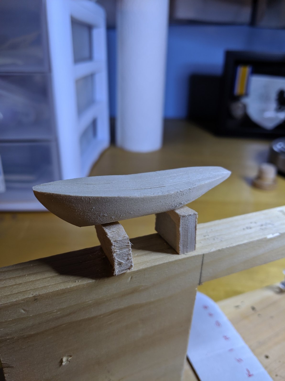
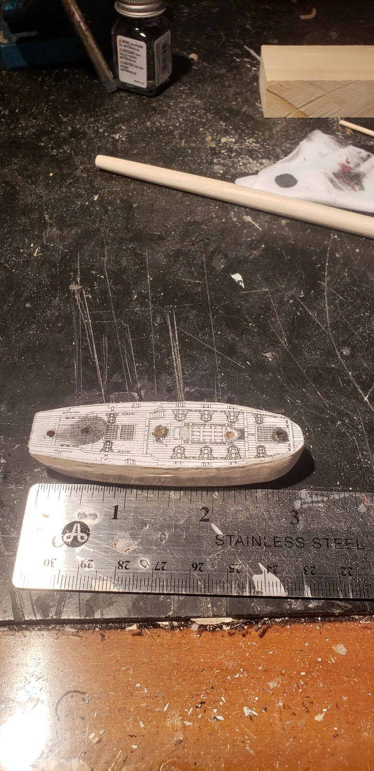
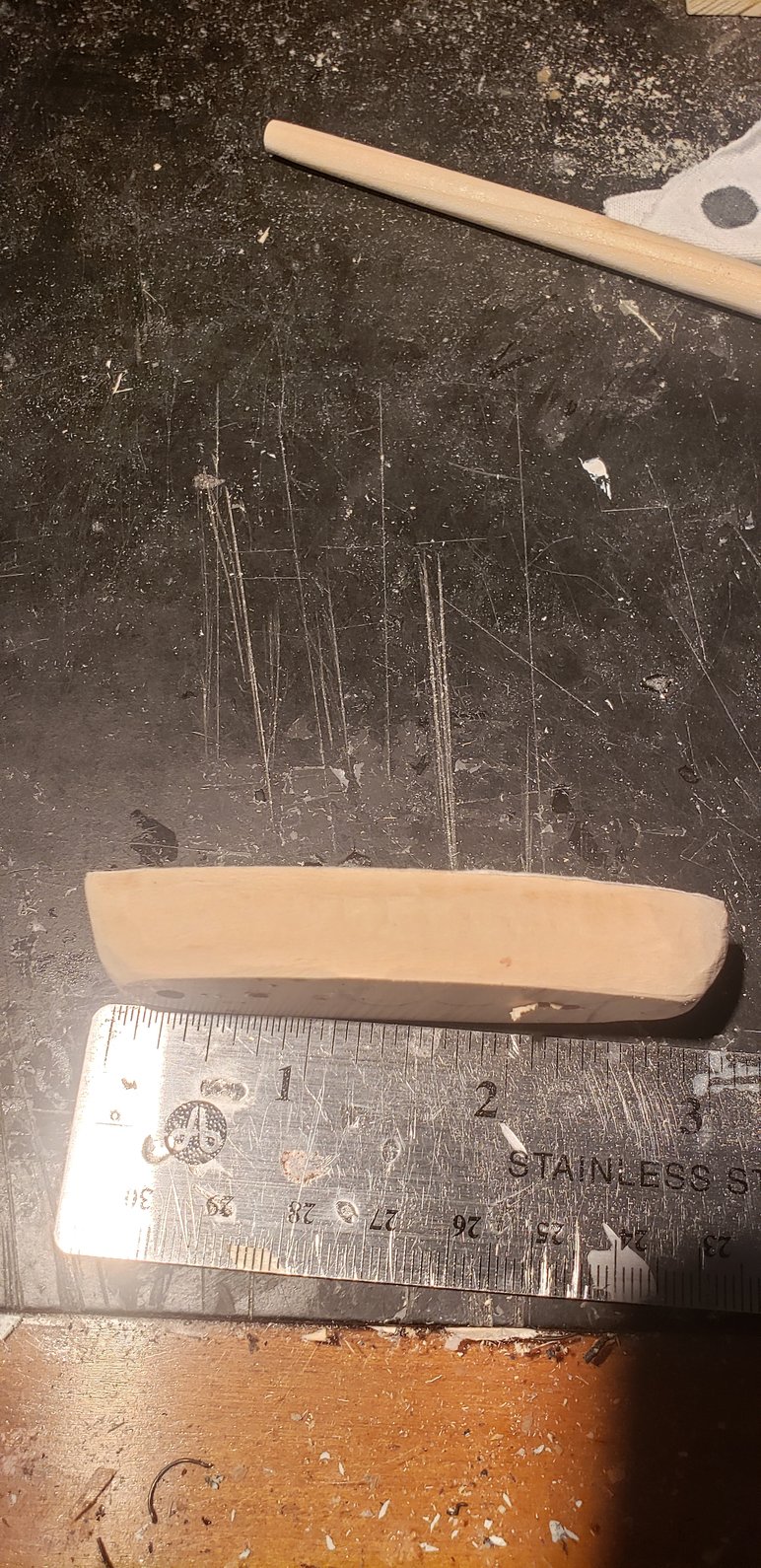
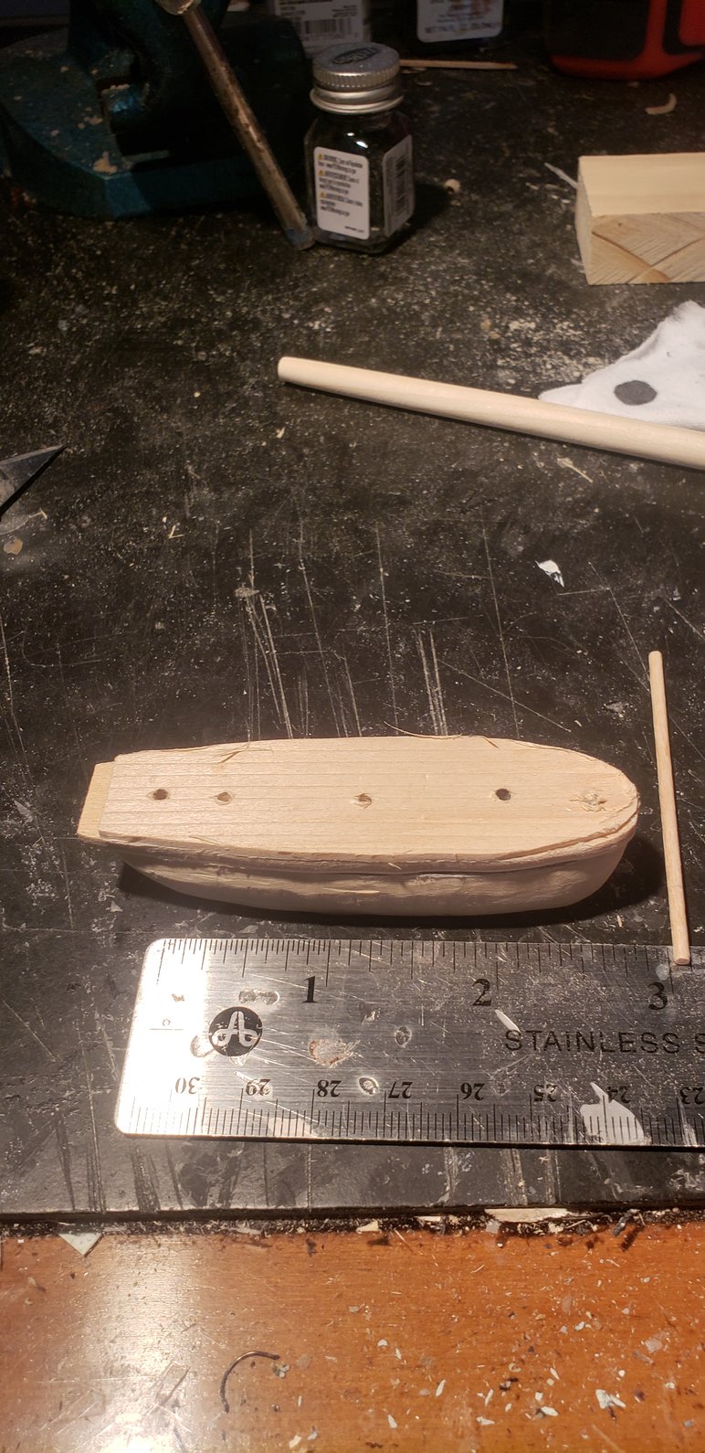
Hi All, I've started on a SIB of the HMB Endeavour, which is a relatively famous ship in this part of the world. I started about a month ago, after I'd visited the replica of the ship, and taken heaps of photos. As it lives locally in Sydney harbour, it was a nice day out! So far, I've shaped the hull, carved out of some nice straight grained soft wood from an old office table, which was about 40 years old. I've also played with masts and spas, with mixed success! The hull is sliced at the waterline, and so far, I can fit it down the neck of my bottle. (Always bonus!) This build is going to take me months, as I have to learn how to do and make everything. So any comments, criticisms, pointers where I'm going wrong, etc will be more than welcome. Thanks. Mick

 14 points
 -

Archibald Russell
lcrcar and 13 others reacted to Alex Bellinger for a topic
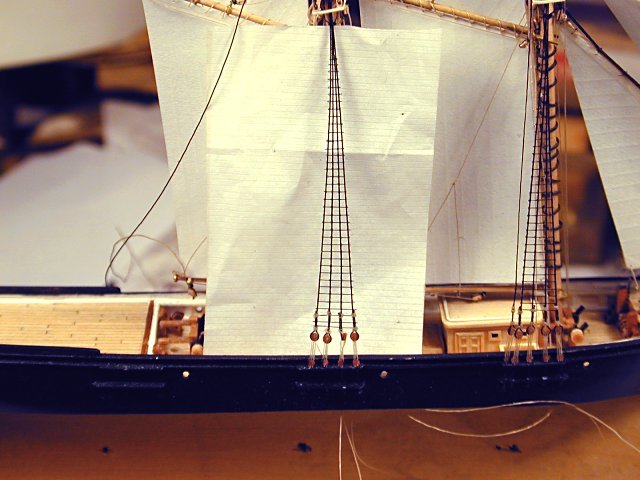
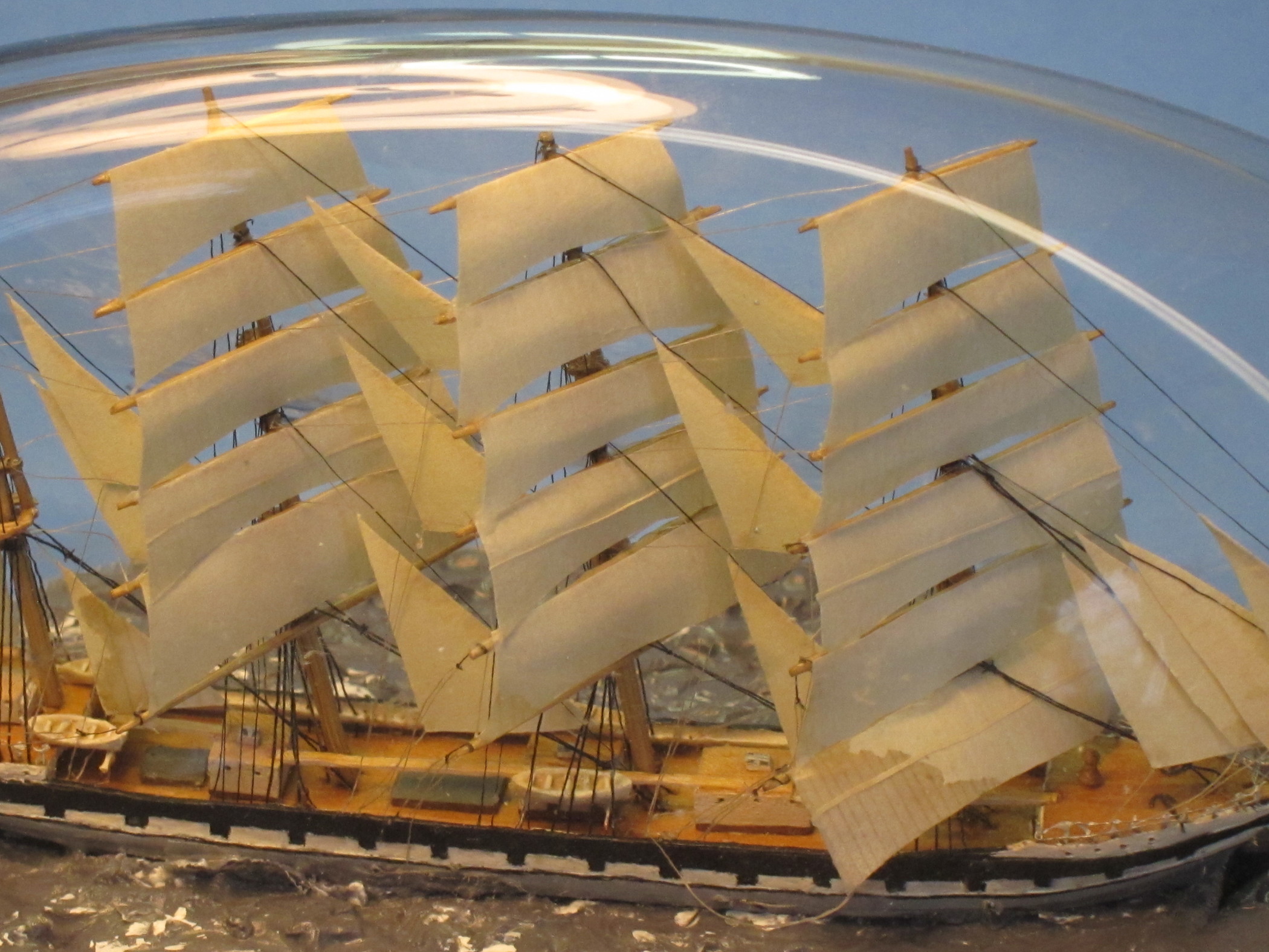
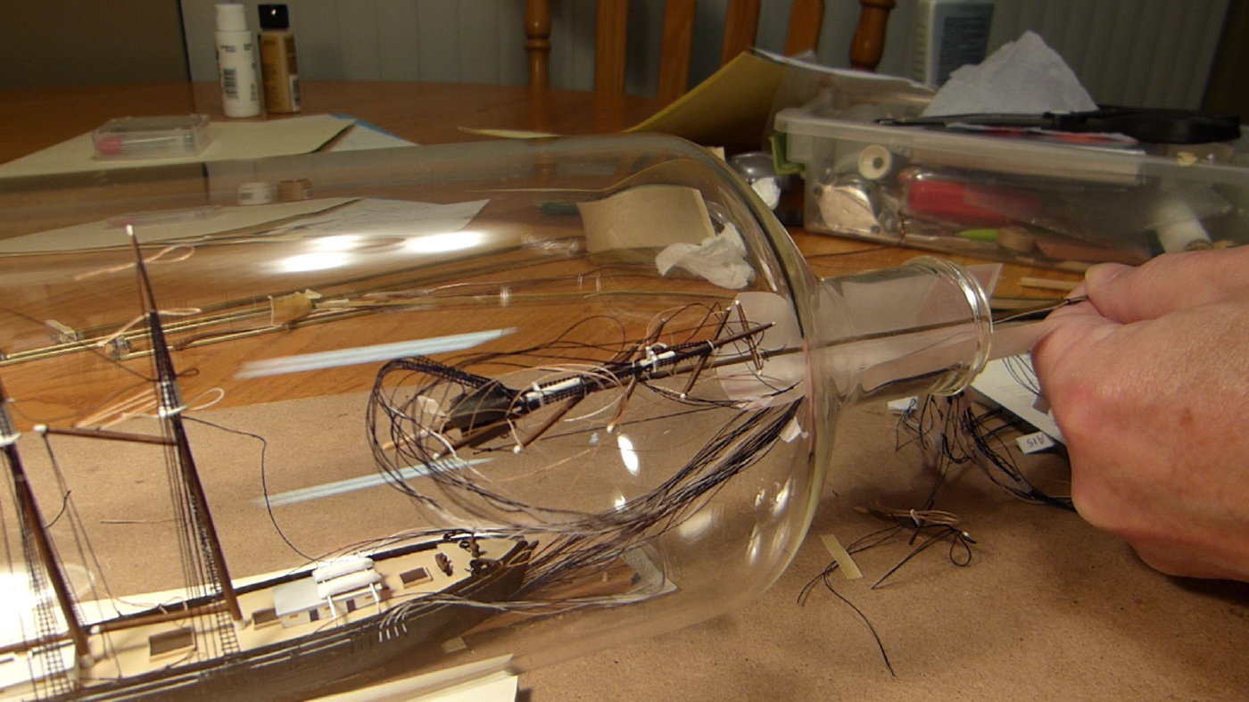
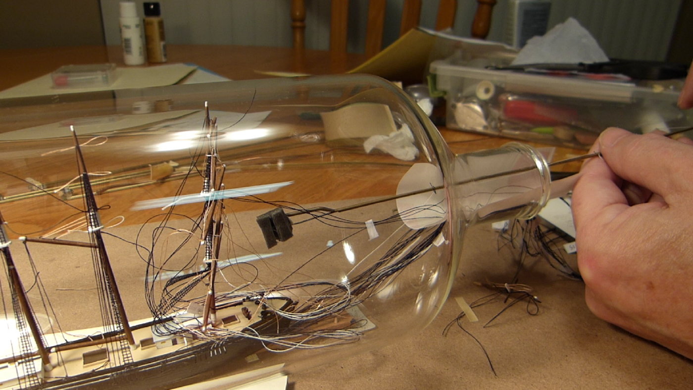
Finally the square sails could be added. The material for the sails is much like what I have been using for years, a light weight paper colored with a warm gray magic marker. Instead of using the point of a pin to scribe the seams or “clothes” of the sails I returned to an older idea and used a hard pencil. Seams made with the pin tend to crack and split, and at this scale that could be quite a problem. In spite of using a #9 pencil, the seams, only on the weather side, look a little too heavy to me. The final details are the boats and anchors, and I almost always put these off until the last. Good miniature boats can be nicely made of paper but I’ve had no success with that technique at this scale. There are carved out of pine and have paper thwarts. Like the catwalk railing, these details may be more a challenge at this scale than they are really worth. But not having them no would look worse, I think, so the attempt is always made. The bottle that renewed my interest in this project is a hand blown bottle by Michael Magyar from Cape Cod. It is obviously intended to recall the classic pinch bottle, but happily is slightly longer and better accommodates a long ship like this bark. My friend and fellow ship bottler Gerry Ross knows Michael and sent one of these bottles as thanks for getting John Guley to complete a prototype of a kit Gerry was trying to develop John and I decided to give it to Charlie Ryan, another ship in bottler, but John got in touch with Michael about ordering more. After some back and forth we ordered 10 and split the order between us. For the first of my five I bottled the 5 mast two topsail schooner Carl Vinnen. The glass clarity is wonderful but the inside shape creates a couple of problems. The narrow corners inside are a little difficult to fill with putty and then get a smooth sea surface. It takes going back over a number of times. The corner on top, above the ship, is so narrow I was concerned whether the upper yards would have been braced around far enough for them to fit in this limited space. The indent on the side of bottle underneath the ship protrudes so far into the bottle the putty base above it is very shallow. But with the deep corners, the bottle takes a surprising amount of putty. But there was an unexpected bonus. Two air bubbles on the port side wound up acting as miniature magnifiers The bottling took about a week between getting her in and feeling all was well enough finished. Most of the difficulty was not having a secure enough bond with the putty sea, so that as I increased the tension on the stays, the model tended to head back towards the neck. I got over this by fashioning a section of coat hanger wire bent to hold the hull in place and taped to the outside of the bottle neck with duct tape. It is the first time I ever tried this, and I wonder if I’d recommend it. But in this case, it worked. The putty was put in the bottle months before. Because of the effects of oil staining sails, I have greatly increased the lead time between setting the putty in and finally bottling the ship. In spite of this lead time, the slight contact with the putty surface when bottling this ship immediately doused lower starboard sails with oil. This may eventually become lighter, but the effected area will always be more translucent than the rest of the sails. It may also spread, though I have rarely seen this with square rigged sails. I first encountered this problem years ago when the late George Pinter from Halifax, Mass, recommended I use plumber’s putty instead of the glazing putty I had been using. It took color well and was easy to shape into the bottle. Unfortunately, the heavy oil content of the plumber’s putty began to stain the sails like this. It also is supposed to never harden completely, and when the putty sea in a bottle I shipped to a gentleman in Texas became detached en route, that was it for me, and I returned to glazing putty. Sadly, this oil staining has returned in the past couple of years, and I need to solve this. Otherwise, this particular model was especially satisfying. We all have early dreams and visions that inspired us to take on this kind of work. For many of us, these are now many years old. This model does not succeed in many ways, and has a number of details that could have been, and should have been better. But it also succeeds enough in fulfilling early inspirations of mine to be encouraging, and give me hope there may well be similarly rewarding models in the future.


 14 points
 -
Archibald Russell
lcrcar and 12 others reacted to Alex Bellinger for a topic
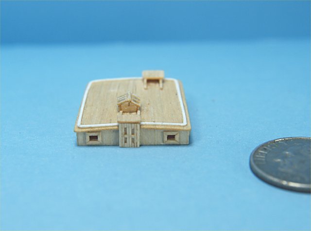
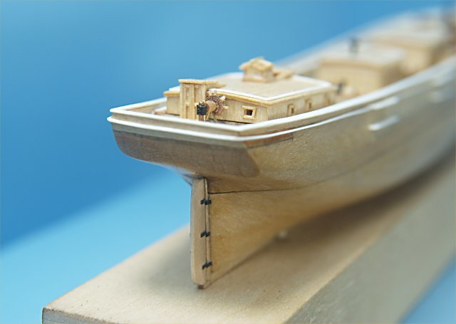
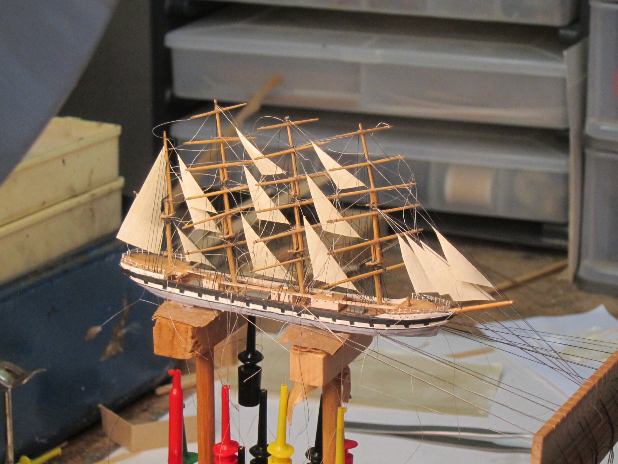
Archibald Russell The four mast steel bark Archibald Russell was built in 1905 in Greenock by Scotts Shipbuilding and Engineering Co., and was one of the last of her type to be built on the Clyde. Built for general trade, she was 291 feet long and had a beam of 43 feet and displaced 2385 tons. She was owned by John Hardie & Son of Glasgow. After years of carrying a variety of bulk cargoes around the world, she was sold to Captain Erikson who operated a fleet of sailing ships, primarily in the grain trade from Australia. Eventually she was broken up in 1949. This ship was unremarkable in design or history, but exceptional as a well -documented and handsome example of her type. Underhill created a very detailed set of plans, including one sail plan with yards lowered and another with sails set. Bjorn Landstrom added a careful drawing of her hull and deck furniture as well as a color sail plan in his popular 1961 book, The Ship. Clive Monk followed Underhill and added her plan to those in the appendix of his 1954 Windjammer Modelling. Best of all, Edward Bowness made the main subject of his thorough 1955 Four Masted Barque. The second edition included information on a number of similar barks, but it grew out of a detailed guide to building an accurate model of the Archibald Russell. She has come down to us as the leading example of this kind of ship near the end of the sailing ship era. She is also well suited to ship in bottle building. Her long shape and complex lofty rig are well suited to a typical wine or whisky bottle, filling the space handsomely. In the early days of the craft it is easy to imagine many of the craftsmen, though perhaps not knowing Archibald Russell specifically, were certainly familiar with a ship or ships just like her. My own model started sometime in the mid-1990s, as a project for one of the ship in bottle classes I was offering those days. It was clearly intended for advanced students and I was not entirely surprised when I got no takers. The plans are my own drawings, taken from the plans in Bowness’ book, and made back in the days when I still believed this extra step was essential for accuracy and developing a familiarity with the ship. Now I am more skeptical about errors possible in this work, especially from careless draftsmanship. But in this case I felt my plans were accurate enough, and the templates were made from copies of these. The model itself starts as a pine core, and bass wood is an excellent alternative. I’ve heard cedar is also good, and I look forward to trying it. The lower hull is hollowed out for the rigging lines, done with some fine chisels and smoothed with files. Although having invested in many fine files over the years, I often return to the files from an inexpensive keyhole set purchased over 30 years ago. For larger scale models I would normally plank the deck with thin strips of wood, but at this scale, approx. 61’ = 1”, there is little point. The bulwarks are added on and eventually I learned working with multiple strips of wood for these makes it easier to effectively get the right sheer. A thin strip is glued horizontally inside the bulwarks to serve as a rigging railing for the shrouds, backstays and sheets. Made of pine, this strip went in very neatly but was later to cause me much woe. As an experiment I went over the outside of the hull with thin strips of paper to represent the hull plating. I liked the results and this did make painting the hull easier, especially the lines along the hull sides. The painting was still time consuming, taking a number of times going back over the strakes and false gun ports to get it as neat as it should be. There are some fine masking tapes out there, particularly the green “frog tape”, but so far I’ve only gotten little results using them at this scale. The deck furniture is varied and involved. There are three houses on the main deck and another, the chart house of the poop. The poop and fo’c’sle are joined by a catwalk that runs over the main deck houses. The hatches have peaked covers. All houses and hatches have brown “booting” around their bases, which was represented by this strips of paper painted the correct color. All portholes are simply simulated by pin holes in the wood. As often before, I lose interest in photography until the rigging starts, although there are a number of things that must be done before it can begin. The railings need to be added to the poop and fo’c’sle. They are made up of nicrome wire, 0.008” for the stanchions and 0.004” for the railings. The former are set into holes at the edges of the decks and the latter superglued to them as they are bet around the stanchions. This is not the best method, I’m sure, but it is the best I’ve managed so far. I’ve tired various jigs to create these railings off the hull but have had two ongoing problems; keeping the tension on the wire even as it is applied to the jig and finding an adhesive that can be depended on. Perhaps those with more experience in this technique can enlighten me. There is also a light railing along the catwalk but I did not seriously consider attempting this. Even the finest materials I have would still be too large for this feature and it would be a considerable challenge to make it without the results looking out of proportion. Furthermore, this railing would be so light a delicate it would probably not survive the rigors of rigging the model, let alone the bottling. Even the more robust fo’c’sle and poop railings took enough of a beating through the completion of the model as to make me wonder whether I shouldn’t have figured out a way to add them later in the process. Among the other things necessary to get done before starting rigging is, of course, making the masts and spars. At first I was going to use hinged “Hinkley” masts because I was afraid masts without hinges would not come back up among all the deck furniture. Unhappy with how my hinges were turning out, I decided to chance unhinged masts, and that turned out to be just fine. As usual, all masts, spars, tops and booms are of bamboo. Again as a concession to the scale, I did not attempt the topgallant spreaders. I find it is easier to rig in topmast and topgallant shrouds before starting any rigging to the hull. All rigging was a combination of fine thread and fly tying silk. The lower shrouds and stays are of the thread and the upper rigging is all fly tying silk. All running rigging is a light brown fly tying silk. It seems simplest to start from the foremast and head aft. Lines rigged in separately, of brown fly tying silk, are rigged in below the stays to support the staysails, and I usually tie these in first to help keep the mast in place and because these would usually be rigged in below the shrouds. Next come the lower shrouds themselves. The thread for these is always waxed. After years of doing this I finally realized the line used to rig the lower fore shrouds can be run after through the hollow underneath the hull to become the main shrouds, and on the become the mizzen and finally jigger shrouds. Similarly, the fore back stays, of black fly tying silk, can become the main, mizzen and finally jigger backstays. Therefore, all standing rigging running abaft the masts can be rigged in using just two lines, one of thread and the other of fly tying silk, making it much easier to make adjustments as needed. One of the difficulties arising from this is having to spend an extended period working with exceptionally long lines. Beading needles are an enormous help in this work with one major exception. I found these needles in three sizes, #s 10, 12 and 13. As most folks know, the higher the number, the finer the needle. In spite of being told a number of times these needles will pass through a hole drilled by a #80 drill, experimenting with these needles I found the hole for a #13 had to be drilled by a drill at least as big as a number #78. Both #s 10 and 12 needed holes at least as large as a #74 (!). Unfortunately my delicate railing inside bulwarks could not take much of the punishment of being drilled by bits this large. I had to repair sections of it a number of times. A further complication is the thinness of the #13 needle eye. Only with great difficulty can any line larger fly tying silk be threaded through this eye, and if you do succeed, that eye with the doubled thread will require a hole larger than the #78 to get through it. So much of the threading of these shrouds and backstays was done without the benefit of these needles and took a good amount of time and patience. Having to do this again, I would try to build a sturdier inboard railing. There is also a braided beading needle which is an alternative. My testing found it needed a hole drilled by a #76 drill. Once the standing rigging is all in I usually added in all fore and aft sails. These are easier to set before the braces go it. All staysails have sheets which are threaded through holes in the rail inside the bulwarks but are not secured until near the end of the entire rigging process. This is because the positions of all the masts shift and I was reluctant to commit a stays’l sheet until I felt more certain all was where it should be. This is the beginning of a time consuming and subtle process as the lifts and braces get tied in. Ships like this bark look best if all the mast rake alike and there is a clear uniformity throughout the rig. The braces have slightly more leverage between the masts than the shrouds, backstays and stays so they tend to draw the masts together. This is what I think of as a “corset” effect and can easily wind up with a fore mast raking conspicuously too far aft and a jigger raking too far forward. To try to maintain control and adjust as needed, I glued the braces on the lee side of the yards and only tied them on the weather side, leaving them free to be loosened or tightened. It also left them free to slip off the end of the yard from time to time, It took a number of days of carefully retying to finally get the balance I was after. This is why the nearly completed model is a chaos of loose ends for so long.


 13 points
 -

Experiments in Card/Paper Ship Modeling
IgorSky and 12 others reacted to John Fox III for a topic
Greetings All, The work on the hull progressed by sanding down all the planking, to get as smooth and fair a surface as I could. I sanded, then applied poly varnish thinned 50/50 with paint thinner until it no longer soaked in. Waited for the varnish to dry, then sanded again. I repeated this process many times. While sanding I could see areas where the planks pushed inwards slightly, and small gaps in the finish. I used Bondo glazing and spot putty, applied with a stiff piece of styrene plastic, to cover the gaps and low spots. Again, after Bondo dried the hull was sealed and sanded. I did this perhaps 3 or 4 times before I had a smooth surface over the entire outer hull shape. Once I had a decent hull shape I used a razor saw to cut through the bulkhead extensions that held the hull to the cardboard mounted on the maple board. The following photos show the hull to this point. Work on this first hull progressed with carving the insides of the bulkheads down to the deck levels. I used a chisel type blade in my knife to do this work. The raised forecastle and quarter decks were reasonably easy to work, while the lower mid deck was difficult. I did add some extra pieces of cardboard to the center keel piece in the locations that would later have holes drilled to accept the mast extensions. All the deck areas were then sanded down to the deck lines on the bulkheads, a small amount of Bondo was added as the extra pieces did not quite come flush with the deck level. The following photos show the work thus far. I next worked on making templates of all the deck areas. I used thin paper cut to approximately the right size and shape at first, then pressed them into locations and creased it sharply at each of the bulkhead extension inside the bulwarks. The paper was removed and cut to follow the crease curves. I traced these templates onto thinner card stock and tested the fit on each deck location to finalize the exact shape for each deck area. A piece of thinner cardboard was then soaked in a bath of maple stain, to saturate it completely and evenly with color. I had tried just brushing stain on the board first, but the colorization was too uneven. Lines were then drawn on the board, spaced 1/32" apart, and the thin board templates used to trace the shape of the decks onto the stained board. These were cut out and tested to fit in their places, but not glued down yet. I also traced the outside edges of the main, lower, deck onto a non-lined area of the stained board and cut waterways for the hull. Following photos show some of this work. More to follow as I work along. Anchor's A Weigh! John Fox III


 13 points
 -
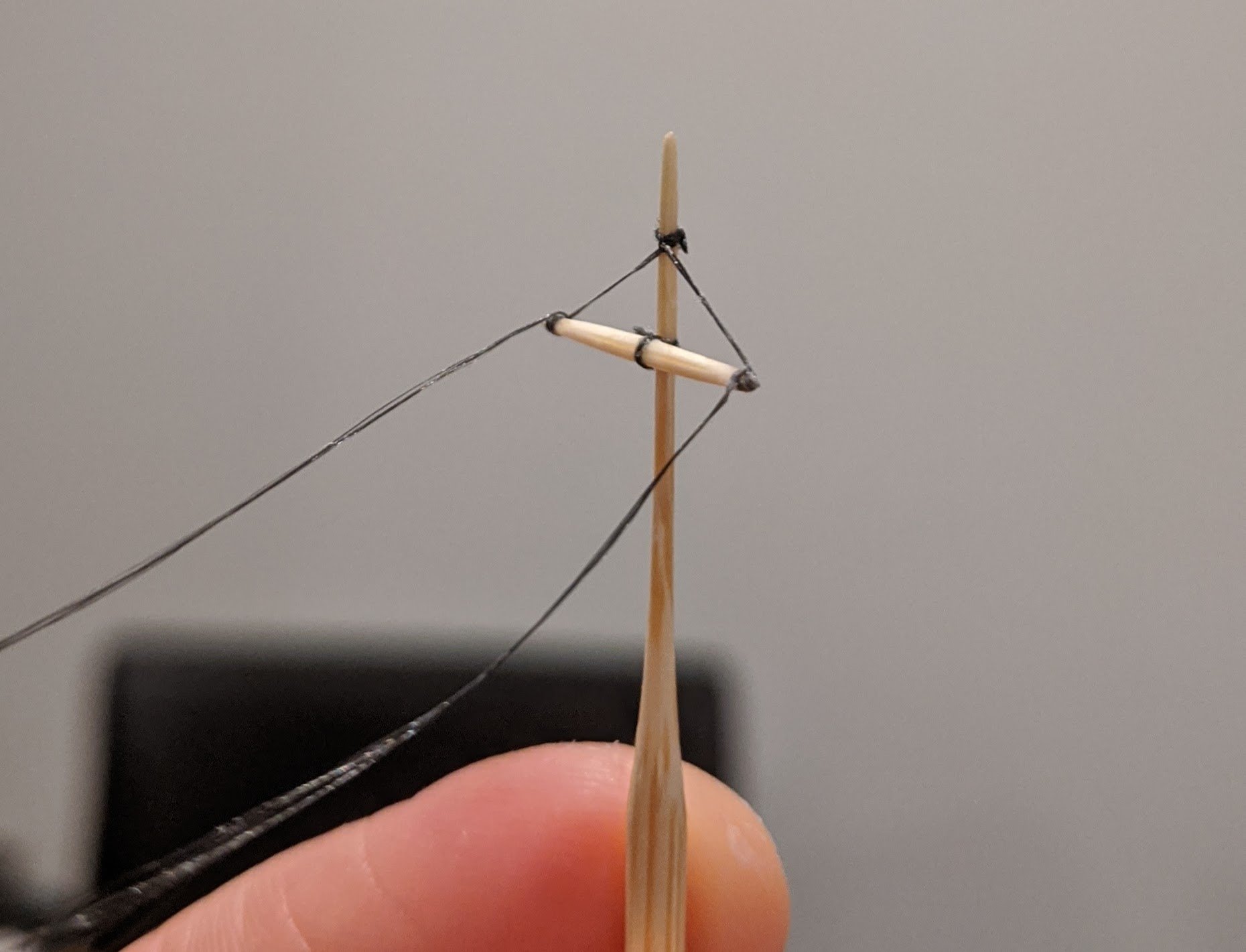
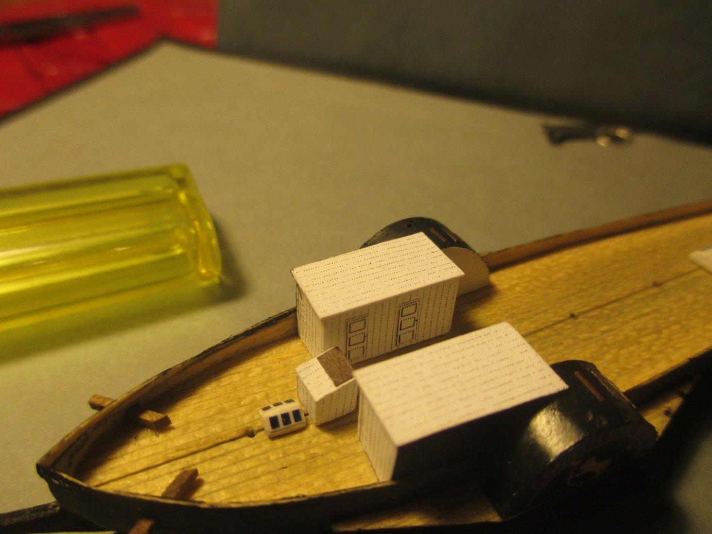
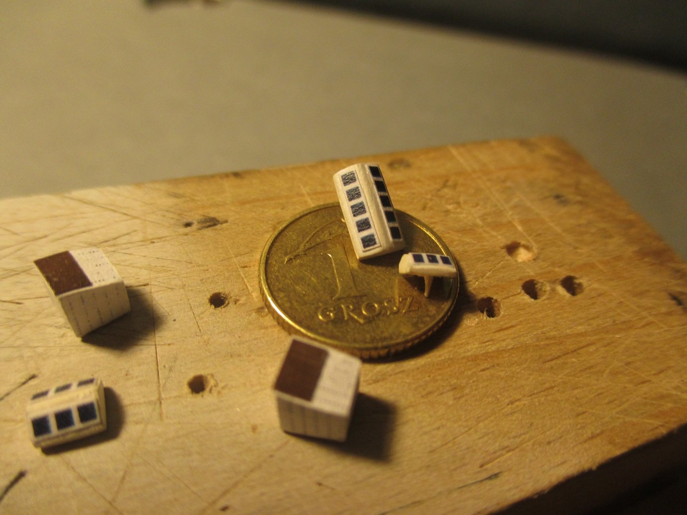
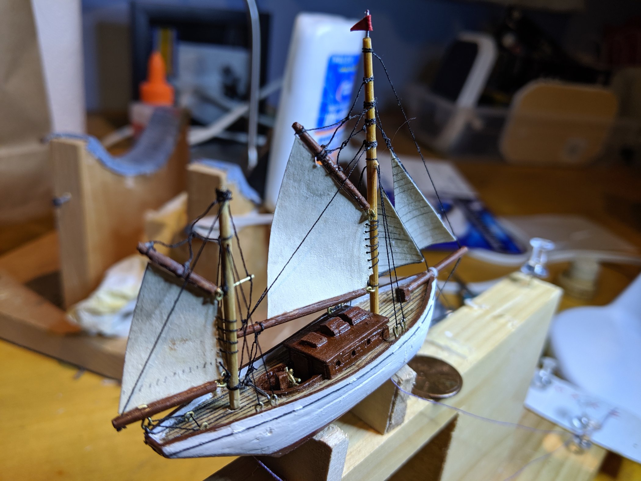
A hoy! I have been working on the masts, yards and ratlines. I bought some fly tying silk and it is very fine. However it is not a single strand, but multiple ultrafine threads laid up together. They are not braided together, which means they easily fray and seperate. But I'm reasonably happy with the results I've got for the ratlines. Shroud lines are standard sowing thread. I set the shrouds up with the correct number of strands and angle, then overlaid the silk ratlines. With tape holding everything in place I dabbed super glue all over it, then absorbed/wiped up the excess glue. Following Onni's advice, I will fix the shroud lines to the mast now, and then glue the base of them to the hull sides later. I made each side of the shrouds on the same strands. This allows me to simply fold the shrouds in half and tie to the mast under the platforms. I've noticed a lot of folks drill holes in their masts and yards to pass rigging through, however it sometimes requires larger mast/yard diameters to allow a through hole. I've chosen to try and keep the mast diameters small, and taper my yards in an attempt to be scale. It means I can't drill through them, I've tried to no success with a no.75 drill. So I'll have to come up with another solution for running rigging between the yard tips, I think it will involve thread blocks. I've experimented with yard braces. It works well I think. There is a small thread block tied to the mast and the yard braces passes through it. When the yard is pivoted to be parallel with the mast (for bottle entry) the line goes slack. When the yard is then pivoted to perpendicular the line goes back to tight. Convenient geometry of triangles and pivot points. My latest problem is how to make the rear cabins. I need to build them up because I haven't carved them out. For shaping the actual windows I can't cut timber panels accurately enough, nor does the grain of the wood allow it. So I have experimented with two methods of creating windows: One is to stamp the shape. So I made a little metal punch to stamp the shape of the window onto a piece of wood that I can then glue to the sides and back. The second is to try and imprint the shape of the windows onto a piece of wood. I bent some tin to shape and sharpened its edges. A light tap imprints the profile. Neither of these methods produce amazing results but it's better than nothing. Does anyone have a way of reliably repeating the exact same cabin window shape? My next major tasks are to work on the prow detail and stairs on the deck. Hope you're all staying safe. Regards, Caleb.


 13 points
 -
James Miller 3 masted schooner
JerseyCity Frankie and 12 others reacted to John Fox III for a topic
Greetings All, Have been working on 2 models of the James Miller at 1:300 scale and thought I would share some progress photos and info. One of the models will be going into an 11" long sodium vapor street light bulb, the other in a wall mounted clock that resembles a pocket watch case, the latter will be static display. I've been working on the models for about 8 months now, on and off. Both hulls are split at the waterline, to allow access to the underside of the upper hull, and to fit through the light bulb opening. I decided to try something different with these models, the hulls are carved from solid maple, instead of the basswood I have used for hulls in the past. It it a bit more difficult to carve to shape, but much stronger. The upper hulls were carved to the decks, then a solid piece was carved to match both the forward and stern decks, the forward longer section was pegged to the deck, the small stern piece was just held in place, then both were carved to the outer shape of the hull. Both pieces were then "hollowed out" to about 1/16" thick. Maple keel was added to the hull pieces, then the interior of the forward bulwarks piece had styrene frame tops added, along with a styrene pin rain added their entire lengths. A 1/32" forecastle deck was then cut to shape, and glued to the tops of the pin rail on either side. A styrene top plate was then cut and glued to the tops of the bulwarks of the entire hull. The bowsprit was made from maple, the jib boom was made from glued maple laminates for strength. The light bulb model had laminated lower masts, to make it easier to add hidden hinges for that model. All the other spars I made from solid apple wood, which is different from my usual techniques. The apple wood is amazingly strong, even when cut and sanded to small diameters, and nearly grain free. Most of the spar attachment points for rigging were cut and filed from various thicknesses of solid brass, thin brass shim material was used to make some of the attachments, like for the bobstays and boom sheet and topping lift attachments. The boom and gaff jaws were cut and filed from 0.20" thick brass, mainly for strength. One of the reasons for the lengthy build of these models is my attempts to try different methods and materials. One of my better "finds" for these models was the use of electrical shrink tubing for the mast hoops. I used a wooden dowel a bit larger than the thickest part of the masts to shrink 1/8" diameter tubing to size, by heating the tubing carefully. A single edged razor blade was then used to cut thin sections of the tubing for the hoops. When I shrank down the upper mast hoops I found the shrunken tubing was too thick, so I used various grades of sandpaper to spin sand the tubing to take the thickness down. I would have preferred to have used brown shrink tubing, but while there are a variety of colors available, brown was not one of them. The cabins for the models were made from maple, started with a core building of 1/32" maple veneer longer sides, with 3/32" maple ends, and a similar thickness maple inner piece for strength. The door and window openings were then cut through the side panels. I then glued 0.010" thick maple "planks" to the outside of the cabin. Very tiny pieces of the thin maple were then cut and glued for the door and window frames. I decided to let one door partially open on each cabin, just to show the hollowness of the cabins, the doors were made similarly to the cabins themselves. All the decks of the model were planked with the same 0.010" thick maple, the maple was hand sanded down from the 1/32" thick veneer that I have a good stock of. The planks were then cut and sanded to size, and a soft lead pencil was rubbed along one long edge and one short edge of each plank. The planks were glued to the decks with thinned white glue.


 13 points
 -

Constitutionen
JerseyCity Frankie and 12 others reacted to Artur for a topic
Continuation Artur


 13 points
 -

Lifeboat COLIN ARCHER RS1 Scale 1/230
JerseyCity Frankie and 12 others reacted to IgorSky for a topic
Finally, the building of the model has been completed


 13 points
 -
What's on your workbench?
Bruce Foxworthy and 12 others reacted to Alex Bellinger for a topic
These are a few shots of my recently completed Charles W. Morgan. I'd been reluctant to post anything about this project because of serious doubts whether it would succeed. It took far too long because I made a number of poor choices and had to go back and redo a number of things. For example, this is the second hull and it took 16 whaleboats to get the 7 that finally went with the model down the bottle neck. My eyes aren't quite what they used to be either and that has made rigging a much slower process. The next project will not be as ambitious.

 13 points
 -
Well I had my first opportunity at ship in bottle repair. It was entirely different than I expected I'd do with a ship in bottle repair but I got it back together. I should have got a picture before I got it back together but when the gentlemen brought it over the mizzen main sail was floating around the bottle totally detached. I had to maneuver it in place and glue it down. Took two hours but I did it. Funny thing with glass ships. There no wiggle room.
 12 points
 -
The first "real" ship in a bottle that I built was the SCHULSCHIFF DEUTSCHLAND. I got married on it in 2013. So it was a very personal event, which has revived the long-cherished desire. Everything is still a bit clunky and crooked, but made with muuuuch love. Including wedding couple on the back.😍


 12 points
 -
Hi All, Hope you are all keeping safe. There has been a bit of talk about mast drilling and jigs, etc over the past few months. I thought I'd kill a couple of hours in lockdown putting together a screed on how I do it and the jigs I've made to help me. Hope its of interest. best Alan Mast drilling jigs..pdf12 points
-
Experiments in Card/Paper Ship Modeling
Lboro and 11 others reacted to John Fox III for a topic
Greetings All, The work on the card and paper clipper model continued with quite a few more sealing and sanding, with small amounts of Bondo. Once I had a decent hull I made up the keel, stem and stern posts out of multiple layers of board. After reading more online about card models I learned to saturate the card stock with thinned down poly varnish, in order to make it stiffer and less prone to fraying when sanding. It also made cutting a wee bit harder, but worth the effort as it shapes up nicer when saturated. I did this by using a large art paint brush and applying the thinned varnish, then letting the card stock dry, and repeating the process until no more varnish would soak into the stock. The keel and stern/stem posts were made from this saturated card stock. I then used epoxy glue to install these parts. Unfortunately, I had to use painters tape to hold the parts in place while the epoxy cured, this resulted in removing the sealed surface of the hull where the tape was attached. It left fuzzy areas, so more sealing and light sanding was necessary to seal the entire surface of the hull again. At this point I used extra prints of four of the bulkheads and the spacer used to glue the bulkhead tops to the board to design and cut out card stock pieces to make up a couple of stands for the hull. The following photos show the results of this work. More to follow as the work progresses. Anchor's a Weigh! John Fox III


 12 points
 -
She's Launched!!!! It's been a while since I've been here, but slowly bits have come together. There is a photo of the ship, rigged, (almost), sitting on the table, one of my launching tool,(launch ramp??),which is modelled after the Amarti tool I used for Hannah, and one of her in the bottle, with the air pump going to get rid of any fumes from the glue. I have the mast handling tool sorted out, it seems to work on the dummy runs, and a few suitable Swann Morton blades in the post, due very soon, which clip onto an extended handle. Now I just have to rig her! Cheers Mick


 12 points
 -
Funnel goes in and then the main mast. Decided to leave off 'Daisy' and the cow shed as I thought the deck could look a bit too cluttered.( It's possible that I can add them later if I want to.) Main mast in place with no problems and then set in the foremast. The bowsprit gave me a few problems as the glue didn't set on the first attempt because the mounting hole inside is made up of a plastic and wood wafer construction, so in the end I used an epoxy glue to fix it firmly. Finally completed GB after several months work but unfortunately I didn't notice that the top flying jig rigging had tangled at the top of the foremast until it was too late (everthing glued!) so there it sits; slightly down from the top of the mast.Slightly disappointing but these things happen in our hobby. The stand is a tribute to Brunel which incorporates a bridge,a tunnel,the Great Britain and of course Mr Brunel himself!


 12 points
 -
Ahoy, It's been a very busy month but I finally managed to squeeze in a few hours this weekend. I masked the channel line and cut grooves down to take the bulwarks. I glued the bulwarks on too thick on purpose. This allowed me to sand them down thinner to shape and allowed me to try and make the join between the bulwark and the hull flush. I will be running a channel along the join to hide it better anyway. I spent a fair bit of time making some little cannons. The cannon barrels are from bamboo skewers turned down and blacked with a felt tip pen. The wheels are bristles from a dust brush. The bases are from bamboo skewers cut/sanded flat and cut to size. Glued together with PVA. I still need to trim the barrel lengths down, right now they are easier to handle. I store them on the sticky side of some tape. Saves them getting blown away. I also experimented making some hand railing for the forecastle deck, again using brush bristles and bamboo flats. I'm experimenting with hatching. Using blacked bristles here. I laid them up, spread PVA all over, then wiped off the excess and allowed to dry. I'm still not sure if I'll use this method, or try another. I also started glueing the bulwark handrails on. I will cap with a thin strip of bamboo flat on top of the black bristle shown below. I'm thinking of buying some fly tying silk to start experimenting with shrouds and ratlines. How do you folks deal with fly tying silk having a flat profile? Not round? I read somewhere that someone tried splitting the threads. Or is that not required and the flat profile is that that noticeable? Thanks all, I hope to post again soon.


 12 points
 -
12 points
-

Colvic Watson 28
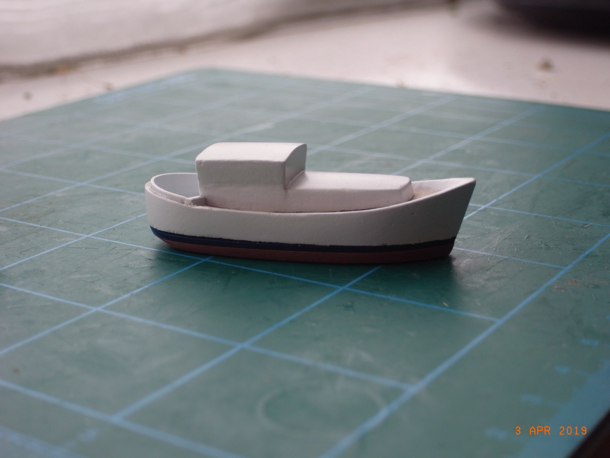
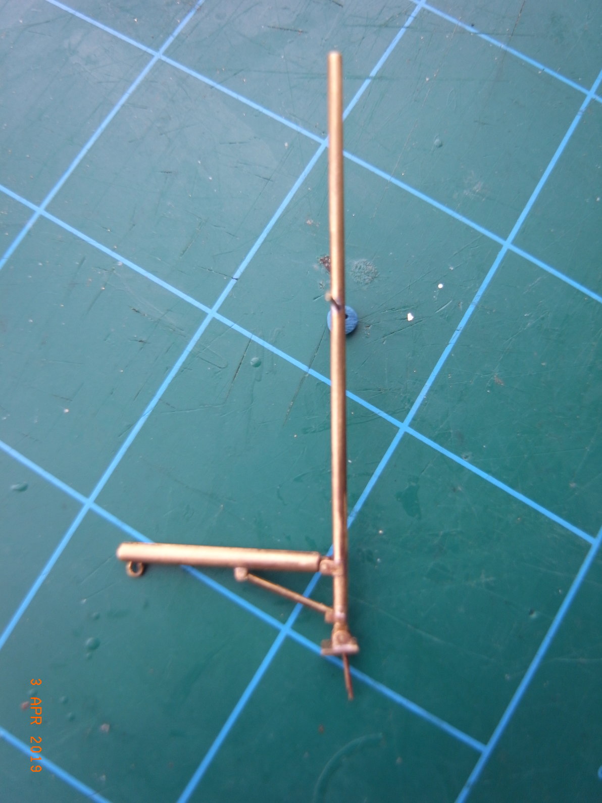
Gordon York and 11 others reacted to exwafoo for a topic
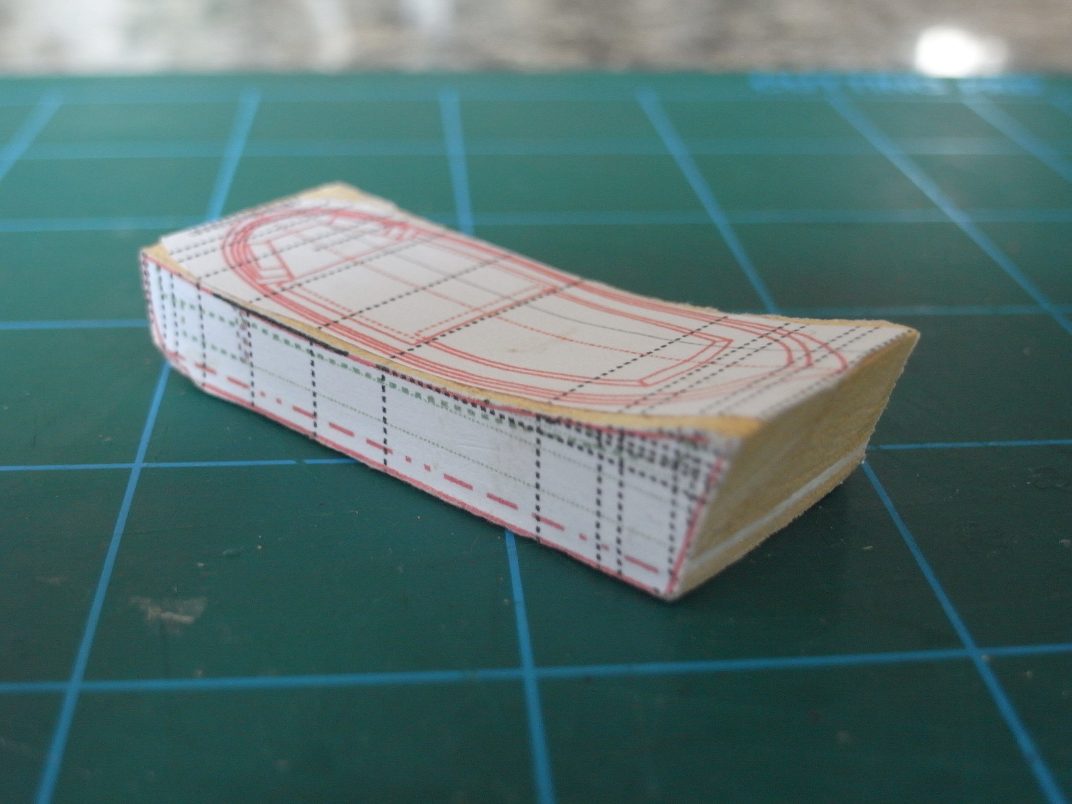
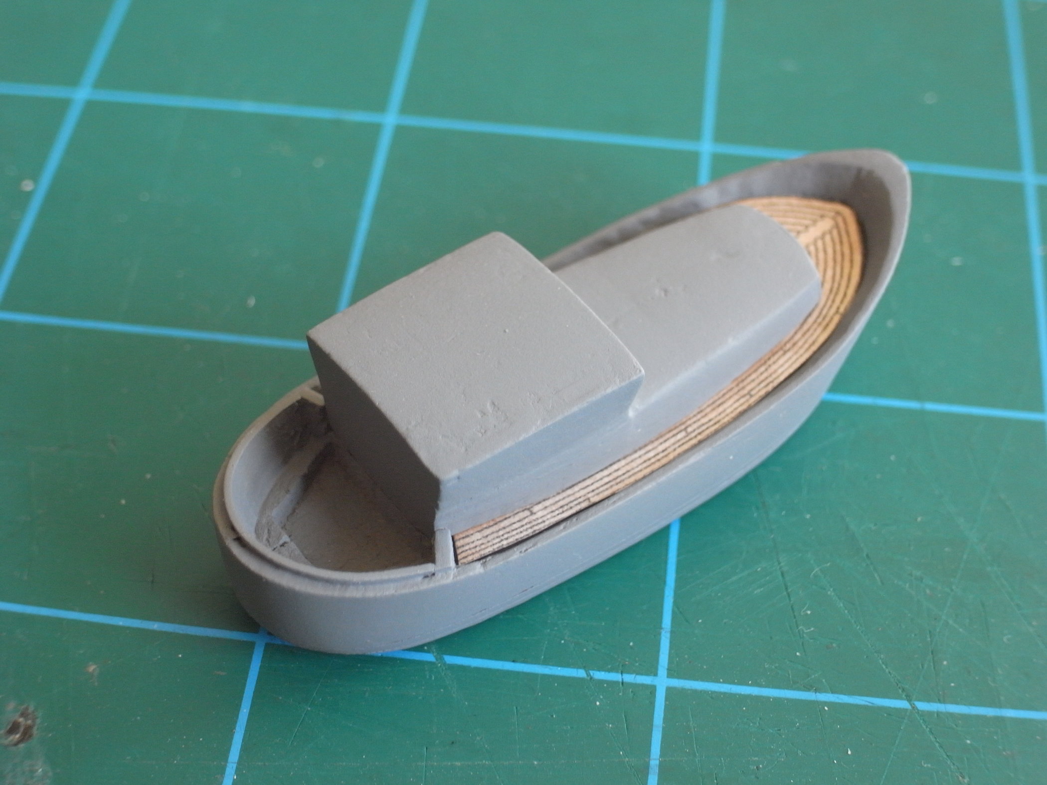
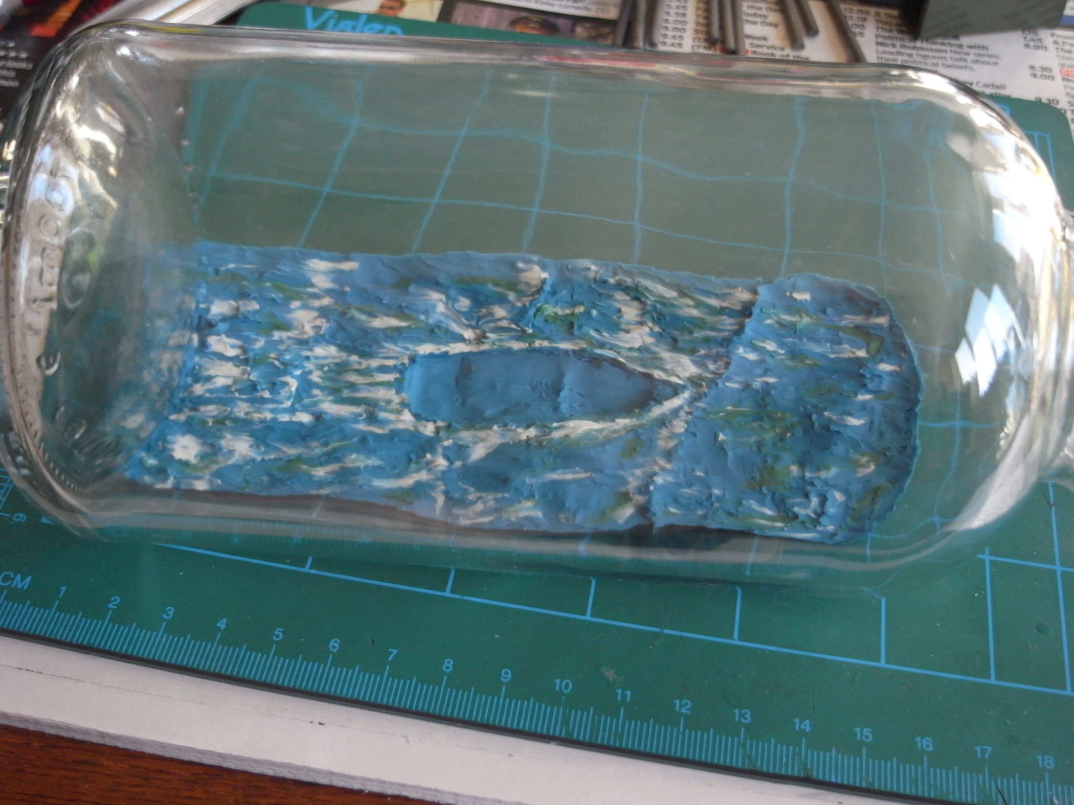
A friend asked me to make a SIB of a boat that is owned by one of their friends. The boat is a Colvic Watson 28 ft as shown in Figs 1 and 2. Figure 1: The drawings Figure 2: the actual boat I had a few other photos to work from as well. I drew up some plans, shown in figure 3. Figure 3: Working plans The hull block was made and shaping started, shown in Figs 4 & 5 Figure 4: Hull block Figure 5: Shaping Started Figure 6: Basic outline. The hull is split just off centre to port and has an upper, mid (from styrene) and a lower. The aim is to give sharp horizontal paint lines for the boot topping, Figure 7: Cabin made, under-coated and the planking. I made the planking from watercolour paper, printed on the PC with different weights of line thickness and shade. I used watercolour paint to try different shades of ‘wood’ colour, then picked the one that looked best at this scale. Figure 9: Top-coated The lower hull sections were painted separately, royal blue for the boot topping and red oxide for below the waterline. Figure 8: Sea started. The sea was made from plasticine, with a description of the SIB and makers name label under it. Figure 10: Starting the woodwork and masts. I used a red hardwood veneer for the woodwork, Small pieces were reinforced with thin CA glue before cutting and sanding to shape. Once attached to the SIB I used diluted clear acrylic varnish on them. The masts were made from brass tube and rods. This SIB had the luxury of actually having a large hinge at the foot of the mainmast. The main and mizzen sails are of the modern variety that are slotted into rails on the mast and are furled on a rotating assembly on the boom. The foresail is furled around a rotating steel forestay. Cutting the slots in the tubing was ‘fun’. I used a small photo-etched saw from http://www.radubstore.com. Took a while but it worked, Figure 11: Main mast Figure 12: Most of the woodwork fitted Figure 13: Masts and sails I used some type of translucent parchment that my wife gave me for the sails. Stitching was simulated using a black pencil, and they were coloured with watercolour, This allowed them to retain the translucent effect, They were a bit waxy, and I had a bit of trouble getting them to stay stuck in the slots on the masts. They held a good shape though. Figure 14: Rigging Underway I used a silver coloured thread for the rigging to simulate the stainless steel on the real boat. The railings were made from brass rod and painted chrome. Figure 15: Almost done. Windows ‘fitted’ I used DIY water slide decals for the windows and name. This is the first time I’ve tried this and have been pleased with the result. A pack of 5 A4 sheets of decal material cost about £5 and I’ve used half of on sheet. First I printed a couple of different sizes and colours on paper for trialing next to the SIB for size and effect. Then printed out 3 sets of the chosen ones on my ink jet, to allow for slip ups. When dry, a couple of light coats of clear acrylic varnish was sprayed over them. Once dry, the decals are cut out, placed in a saucer of warm water and when they float off of the backing are applied using a wet paintbrush and very gentle use of tweezers, left to dry then varnished over to seal and protect them. They went on very nicely first attempt. Figure 16: Ready for bottling Figure 17: In the bottle. By special request, the lighthouse is an attempt at Walney Island Lighthouse at the north end of Morecambe Bay where the owner sails to sometimes. Regards to all Alan


 12 points
 -
James Miller 3 masted schooner
Alvaro004 and 11 others reacted to John Fox III for a topic
Here are some photos of the second James Miller model. It is housed in a 9" diameter clock that was made to look like a pocket watch case. The case is actually cast bronze, quite heavy.


 12 points
 -
How do you make ratlines?
tazam0827 and 11 others reacted to John Fox III for a topic
Greetings All, Here are a few photos taken while adding the ratlines to the shrouds on my James Miller models. The jib was made from 1/16" thick maple veneer, holes drilled to match the distance between ratlines. The line used was 8/0 fly tying thread, rigged as shown in first two photos. 3rd photo shows the jig fastened to the shrouds with an insect mounting pin at the top and a pair of miniature clothes pins and a small piece of bamboo split down on the bottom. CA glue was applied to all points that the ratlines behind touched the shrouds. The shrouds for these models was made from 3 pieces of 8/0 thread made into rope on my miniature rope walk. The final photo shows the finished job, after cutting the ratlines at the outside edges of the shrouds. Hope that helps!! Anchor's A Weigh! John Fox III


 12 points
 -
And finally, Jack took his place on the mast.


 12 points
 -

What's on your workbench?
tazam0827 and 11 others reacted to JerseyCity Frankie for a topic
I’m doing two SIBs at once. One is HMS Ramillies and I’ve got a build log going for her here on BSB. But the second one has no build log, it’s a three masted barkentine with no name and here is her photo. I’m enjoying doing two ships at the same time since some aspects of the project can be done simultaneously and thus are more efficient- like melting and pouring the plasticine sea material. Otherwise it’s good to be able to turn away from one project as it gets stale and go to the other project the following day, alternating. The square rigged warship is done but not inserted and I’ve got half the sails yet to bend on to the barkentine.they should both be complete within a week. Then you likely won’t see me on this website for a while as I will return to my larger, static, not SIB Model Shipways Brig Niagara. So you see in the bigger picture of my modeling life I am also alternating between projects: I built the Niagara to the point of completing the hull and deck furniture and stopped to do these two SIBmodels and when they are complete I will return to Niagara to begin spars and rigging, which will take a long time. Alternating between project helps me to stay enthusiastic about each and not become bored with either.
 12 points
 -
James Miller 3 masted schooner
Lboro and 11 others reacted to John Fox III for a topic
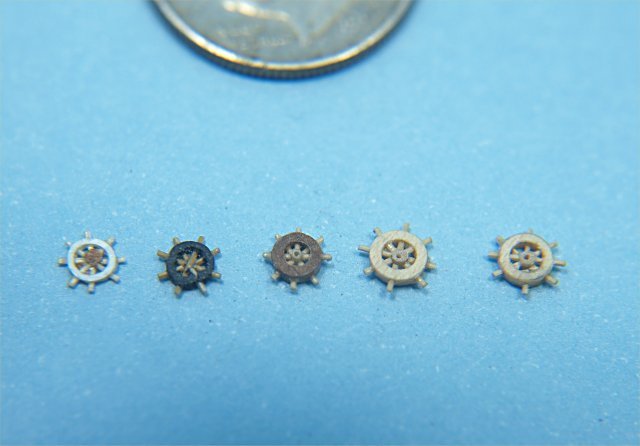
Greetings All, Latest work on my James Miller model pair. Finished up all the cabins and deck structures, first two photos show the cabins. Nest two photos show different views of the fife rails that are situated around the 3 masts. This ship had an interesting feature of ratcheting windlasses, they are the black circles just inside the windlass with the small tubes sticking out at 45 degree angle. They would turn the windlass on the down stroke and ratchet freely on the up stroke, wood or metal poles were pushed into the tube ends to operate. Never saw anything like this before and found it an interesting feature to work out in miniature. Fifth photo shows the main anchor barrel windlass, the fore deck capstan for raising the anchor out of the water and the ship's wheel. The last photo shows some of the many attempts I made to manufacture the ship's wheels needed for the two models. The first was made by simply gluing some drawn down bamboo together, then cutting circles from .005" thick styrene plastic, and gluing them to both sides of the "spokes", added a tiny center circle of paper. The second attempt I made using shrink tubing, larger diameter tubing that was shrunk down around a small diameter drill bit shank. The shrinking increased the thickness of the tubing, I then drilled holes and inserted the same bamboo spokes. Both of these methods worked OK, but did not have a decent method to attach to the horizontal "arm" of the entire mechanism. The third and fourth wheels were made by drilling a hole in the end of a piece of apple wood, then sanding the outside to get a thin walled tube. Holes were drilled in the tube near it's end, and the bamboo spokes added. The difference with these was that I made an extremely small diameter tube from apple wood, and glued the spokes to this in the center of the wheel. This gave me the perfect method to mount the wheels. The last wheel shown was made by making up a cross grained plywood from nearly paper thin maple wood, then drilled the holes and adding spokes and center piece. I had tried this earlier, but had difficulty drilling the holes without splitting the wheel. On this final attempt I saturated the inner and outer surface of the wheel before drilling and that seemed to work. Sixth photo shows the 100 apple wood blocks I made for the models. There are 40 double and 60 single blocks, my "guestimate" of the number needed for the two models. The remaining photos show the deck structures on one of the models, non of the structures is permanently mounted at this time, I just placed them as well as I could for the photos. I need to mask off the deck areas to air brush the hull parts, so needed the clear decks to make it easier to tape from cap rail to cap rail for masking. Be happy to answer any questions anyone might have. Anchor's A Weigh! John Fox III


 12 points
 -

Mast handling tool
James w rogers and 11 others reacted to DavidB773 for a topic
Hey, all. Here’s a tool for putting masts on our SIB’s. It lets you guide a mast through the neck of a bottle horizontally and then rotates the mast to vertical to its place on the hull and then releases it. Basically, it’s a small diameter brass tube with a steel wire in it that is attached to a link that pivots. I don’t intend to write a novel and I don’t think anyone wants to read one here so I’ll try my best to explain. It’s probably obvious that moving the wire causes the link (wood material) to pivot. The pivot is a straight pin that was bent to a 90 and epoxied to the brass tube. The two barbs on the link are clipped ends of pins. The sticky backed foam is stuck to the barbs and the blue tape helps. The foam has a slot for the mast. An important part is what I would call the release wire. It creates tension with the foam until removed. An important part is after the mast is guided in and the wire is pulled slightly to rotate the mast to vertical and then placed in the hull, the tool needs to be released. This is a critical time because the mast is somewhat attached to the hull and positively to the tool at the same time. A careless movement could cause breakage. Here’s what to do: attach a thread to the loop on the release wire to pull the wire out. The tool will immediately disconnect from the mast. In the pics, note the range of the rotation that be had; only 90 deg. is basically needed. The first pic shows both sides of the link and the opposite end. If you make one for yourself, I would stick with the small brass tube simply to avoid putting weight on a delicate mast after it’s placed. The release wire does the holding so the foam needs to be soft. I'd be glad to answer any inquires and thanks for taking a look. David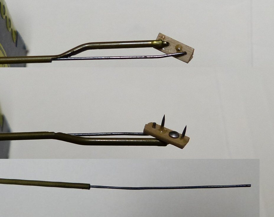


 12 points
 -

Second SIB - S.S Rebecca
Jeff B and 11 others reacted to Capten Madog for a topic
So, as promised I said that my second ship im a bottle attempt would be the Porthmadog built S.S Rebecca. She was the first steamer in the port, loved by the young & hated by the elders. She made weekly visits to liverpool from the port with supplies. The ship model is made from wood painted with acrylic paint. The steam, some strands of wire wool. The stand I constructed entirely from driftwood found in the local bay. The white plaque on the stand is polished bone with the name & date scrimeshawed onto it. I am fairly happy with the result. But as soon as I corked the bottle she was there to stay the way she was. atb Capten M


 12 points
 -
Image captures of video of the foremast installation.


 12 points
 -
Constitutionen
James w rogers and 11 others reacted to Artur for a topic
Continuation Artur


 12 points
 -
So the next part is adding on to the stern bulwarks. I cut out part of the plans to get the sizing that I needed and then cut out a piece of wood to glue in place. I soak the wood for a couple minutes and then glued it to the top of the bulwark. After I send the bulwark down I work on the rail to go on top of the stern bulwark. I cut out another 1.5 mm piece soak it for a a few minutes and then do a grain break at the very end to give that lip between the two rails. Then I glue it in place. I send that piece down to thin it out and then move on to the stern cabin. I start with the front of the cabin that will be on deck cut out a piece that fits in the place where the cabin will be and then sand the top edges to round it out. I decided to cut out the door on this model this is more for my own experimentation it doesn't have to be done as part of the beginners build. For the door typical I'd go out a piece of paper paint it and then glue it in place I wanted to try this out since the cabin is open and I will glue the door hinged open so that it looks like you can walk inside. After the front of the cabin was placed I put in the back of the cabin this is kind of the same thing placing the piece sanding off the top edges to round them out and gluing it on.


 12 points
 -
Constitutionen
Landlubber Mike and 11 others reacted to Artur for a topic
Continuation Artur


 12 points
 -

Small topsail schooner
Alvaro004 and 11 others reacted to Shipbuilder for a topic
All ready for sea. Bob.thumb.JPG.175926968c2e48f1ab2131eb829e3c57.JPG) 12 points
12 points -
Final touches.


 12 points
 -
Flying Foam
AndrewH and 11 others reacted to Shipbuilder for a topic
Topsail schooner. Bob 12 points
 -
Please find further photos


 12 points
 -
Latest Drawing
Moab and 11 others reacted to Shipbuilder for a topic
My latest sail plan drawing, completed today. Bob 12 points
 -
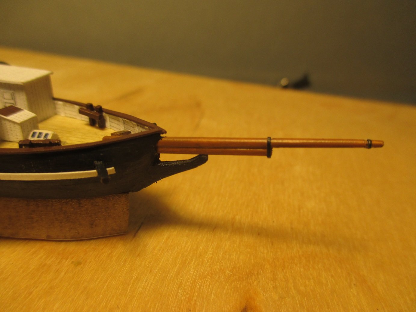
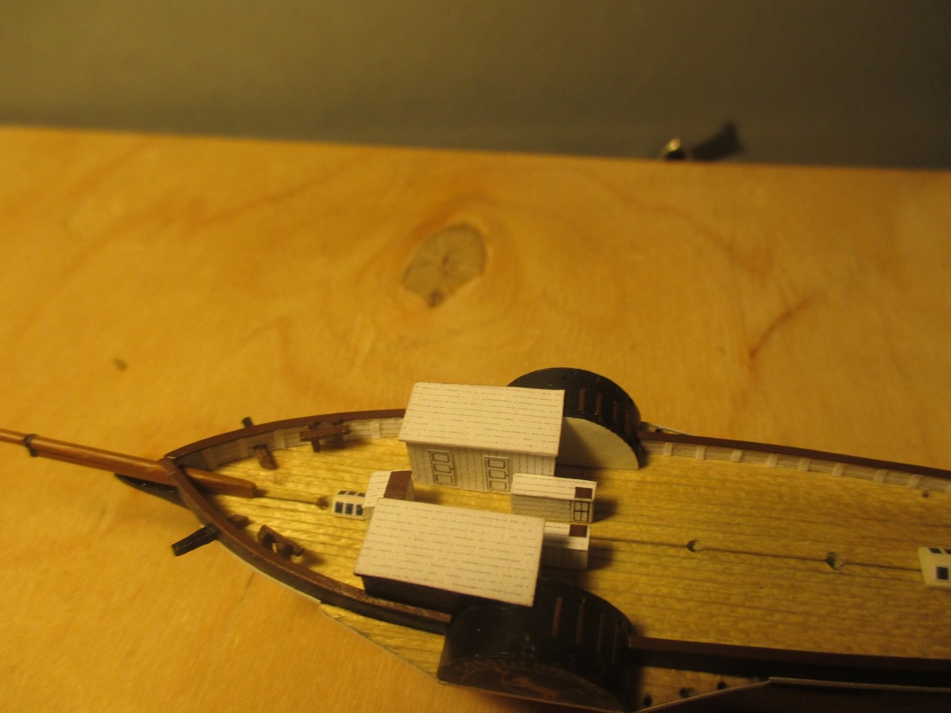
Ahoy, I'm attempting my first SIB! I'm basing it off Alan's (exwafoo) Black Pearl plans. But more with a USS Constitution colour scheme. It is to go into a fittingly named, Captain Morgan - Black Spiced Rum bottle, 77mm internal diameter with an 18mm neck ID. I've taken inspiration in terms of aesthetics and build techniques from many of the build logs on here. I really want the ship to fill the bottle, as you say, so I have slightly stretched the plans to make the ship longer. I'm too scared of splitting a hull down the middle into left and right, so I will split it at the waterline, and add a small section for the rear high section, see sketch. It will be too tight to have fold down masts this way, so I will assemble them in the bottle and rigging and shrouds will pass through the hull, in a similar fashion to David's W. H. Dimond (DavidB773). I like the idea of the full ship hull being displayed, so I won't be doing a sea. Thus, the lines that need tensioning can't come out under the waterline... I'm thinking I will pull them up through the deck, glue, trim, and cover with deck items, like life boats, grating, etc. I'm trying to familiarise myself with all the terminology, and methods of rigging. Please feel free to pick apart my sketched plans below and let me know of any improvements or things to watch out for. Also, even though I will most likely be painting the hull, should I buy some Basswood to make it out of? Does it make thing a heap easier? I'm currently planning on using some Tasmanian Oak I have left over. It's a commonly available hardwood timber down here in Australia. Kind Regards, Caleb. Some methods of how I intend to do the masts and yards. Are loops required for the top of the square sails all the way along the length of the yard? Or were they only ever held at the corners/ end of the yards? How I plan to split the hull in three to make it fit through the neck. Showing how the rigging can tensioned through the deck. Is this mostly accurate? Showing Yard rigging.


 11 points
 -
Experiments in Card/Paper Ship Modeling
IgorSky and 10 others reacted to John Fox III for a topic
I've been intrigued lately when viewing build logs on the NRG web site, among other places. Decided I would give it a try and see how it all works. I started by viewing the vast number of CAD ship plans I've developed over 40 years of modeling sailing vessels. I was interested in something fairly simply, but one I had enough information already drawn up in plans. I ended up settling on the clipper Flying Cloud. I drew up the plans 27 years ago for a ship in bottle model at 1:750 scale. For a card/paper model I decided on a scale of 1:350, making the hull slightly over 8" long. I spent a little time taking the original plans and adapting to a bulkhead type of model. My original was a carved solid hull. The following images show my drawings for a card/paper model. The .jpeg images were exported from QCAD, as exports the line weights are too heavy. I have the same images as PDF images if anyone is interested. The solid lines are cut lines, the dotted lines are where parts get glued on. The "X"'s are areas that have added thickness, to make a solid area for the masts. The waterline is not a cut line. The rectangles outside the hull lines designate where spacer pieces would lay. The following drawings show the spacer pieces. These were drawn before I actually thought it all out. In the end, though designed to be single pieces that slide into the gaps between the bulkheads on the horizontal dotted lines, that would make it too difficult to glue and cutting it off later. I ended up simply cutting individual pieces and gluing them in place. The material I chose to work with as the cardboard from cereal and facial tissue boxes, i.e. Special K and Kleenex. I cut large pieces from the boxes, then cut my plan prints to fit the cardboard pieces. I used Elmer's Craft & Art spray adhesive to attach the prints to the board. I sprayed the adhesive on the back side of the plan prints and the non-colored side of the cardboard. At first I sprayed the adhesive until I saw it clearly on both print and board, then attached them. Found out after the first one that I put way too much adhesive, and it was globby and stickier than heck. From then on I just did a quick spray about 4" from both, once left to right and once right to left, and that worked out well. I then cut out all the individual pieces and doubled them with the print side out and slid them together to see how it would fit together. The fit was tight on places, but it did go together. I found that the cardboard used was not a really as solid as it appeared. In the tight fitting areas the board collapsed inward, which resulted in places like the outer edges of the bulkheads spreading apart a small amount. The hull shape looked fairly good, but the collapse area of the keel piece caused it to curve slightly. Fixing the problem for me was to take an extra print of the page 2 plans and glue it to a much heavier piece of cardboard. Then gluing the square areas on the top of the bulkheads over the dotted lines of the print. That aligned things nicely, but found that the heavier board base went into a slight curve. So, used a few small screws to fasten the heavier board piece to a solid piece of maple. Since this was my first foray into card/paper ship modeling, I did not take photos of the individual parts before assembling them together. I was not at all sure that this first attempt would turn out well enough to bother continuing with the build. The photos above show the hull after the first layer of spacer pieces were glued in. You can see a few places on the first photo where the doubled bulkheads spread apart slightly due to being squeezed where they fit onto the keel piece. The photo above shows the hull with the second spacer pieces glued in place. I made to cut these so that the bulkheads were pushed together. I then applied CA glue to all the joints between pieces and covered all the edges.


 11 points
 -

What's on your workbench?
James w rogers and 10 others reacted to Onni for a topic
Just completed Hms Campbeltown (ex 131 Buchanan) depicting the raid on St.Nazaire docks in 1942. Not that easy to depict a dockyard in a 75cl bottle but you get the idea.


 11 points
 -
Here's my final result, Charlotte Rhodes. I kept an informal log of how much time I spent and what I spent it on. Came out about 54 hours, with 10 spent on the hull, 8 on launching and finishing it in the bottle, 6 on the deck furnishings, 6 on the stand, 5.5 on the mast and spars etc. I actually thought it would have been more like 80 or 90 hours. Did anyone else ever track their hours?

 11 points
 -
West Country Trading Ketch Bessie Way back in 2016,when the world was normalish, the Royal Yacht Club asked the European Association of ships in Bottles to help fund raise for the UK Olympic Sailing Team by building and donating SIBs that had had the sail signed by a team member. I built two SIBs of this ship, see Build Log called ‘Going for Gold Build – Bessie’, so I won’t repeat that part of the build. I actually built 3 SIBs, using the third as a trial ship for some techniques, such as split hull, that I had not used before. Up until last year it sat on a shelf unfinished. I then thought I’d carry on with trial methods in the form of small blocks and dead eyes to see how I got on. I made the blocks from a strip of hardwood veneer. It was a mixed packet of off the net so I’m uncertain what it actually was. The strip was 0.75 mm thick, 1 mm wide and about 10 cm long to give something to grip. I drilled 0.5 mm holes along the length at 1 mm intervals, then applied a diluted acrylic varnish to strengthen the wood strip. After clearing the holes, I filed notches all round as shown in Figure 1, then cut the blocks off. I held them in a pair of tweezers that have a sliding lock, Figure 2, to lightly sand the corners. The tweezers were then held upright in a small vice and the block stropped with thin buff thread with a touch of glue on the thread and knot. Figure 1 Figure 2 I then set about the running rigging as shown in Figures 3 & 4. I know that these blocks are a touch too big for the scale, but it was a proof of concept. I’m happy enough with the result. To form the dead eyes, I tried a method I saw on a page on the net somewhere a number of years ago. A small jig is made, Figure 5 left hand side. I used 0.5 mm brass rod in a bit of wood. Wire is wraped around the posts as shown. The wire is then removed, the shroud threaded through it, positioned and glued in place. The centre of the wire circles is filled in with glue mixed with black paint. I actually used thread on the jig as I did not have any wire of the correct size, and stiffened it with dilute PVA glue, removing the assembly before the glue cured completely. Figure 4 shows a close up of the dead eyes installed. Figure 3 Figure 4 Figure 5 Figure 6 shows the completed SIB before bottling. Figure 6 Then, CRACK, the mainmast broke in the bottleneck, Figures 7 & 8. Not a happy camper. Figure 7 Figure 8 It took a while, but I fixed it by turning the break into a hinge using a thin piece of brass so it would not break again. Circled in red in Figure 9. The brass rod sticking out to the right is my mast holder tool. Figure 9 Figure 10 shows it nicely bottled and dust free. Figure 10


 11 points
 -
A hoy! I finally cracked the rear cabins and am happy with the result. The windows and stained glass are printed paper printed with a yellow grid pattern. To get the arched window frames raised, I bent a brush bristle in a tight radius to form a U. I then trimmed each side to length and glued their ends together. These got glued over the top of the printed paper, which got glued on top of a thin strip of wood. I capped the top of the windows with another piece of wood with a rounded edge for the roof. This rounded piece is slightly thicker than the first strip of wood. This allows it to hang over slightly which I like the look of. I beveled the corners of the side cabins roof with the rear cabins roof, again, just for looks. After a few attempts I made a helm I am happy with. I first made the spokes by lining up 8 bristles, I did an initial squaring off cut and then a final cut. This got all their lengths the same. Then I curled another bristle around a tight radius to make a coil. I then cut across the coil in the direction of its axis. This created a neat little circular ring. I drilled a hole in some scrap covered in double sided tape, and put the over length helm axle in the peg hole. This allowed me to line up all the spokes up against the axle. i removed the axle and the spokes stayed in position thanks to the double sided tape. I placed glue on the axle, placed the ring on the spokes and inserted the axle back in. After drying I could pry away the double sided tape, trim the axle length and I had a helm wheel! I also made the longboat using the plug and watered down PVA method. I found waxing the plug before layering it with PVA soaked tissue made it a lot easier to remove the dried mould. I added some seats out of some thin timber I cut down. I also made a grid pattern of bristles for the grating. I also added some stairs into the deck. I later coloured the walls black to add a bit of depth perception. I added some more handrails. I'll post again soon with details of sails and some more questions of course.


 11 points
 -

San paolo 1743 xambekk malta.
IgorSky and 10 others reacted to James w rogers for a topic
Coming along.


 11 points
 -
Working without plans or proper procedures is a bit of a chore. I had to manufacture some of my own parts like dead-eyes, braces and mast hoops. I rigged the yardarms onto hoops so that they are adjustable instead of gluing them directly to the masts as I think was the intention - which would have been hard since I don't have plans that tell me where they should be glued. So I'm either making things up as I go along or researching other models to figure out what things should look like. I've used parts left over from some other kits I've built and I borrowed the mast, gaff and boom rigging scheme, so now the model is part 18th Century Long Boat, part 19th Century Baltimore Clipper and part 20th Century fishing schooner - a real "Frankenboat". Actually I now refer to it as my "Plague Ship". The photos don't do justice to the amount of work I put into it. I had to stop at this point after my hand cramped up while trying to belay the lower yardarm. I can't figure out if this yardarm is suppose to have a sail on it or was it just a brace? I have no sail plan for it but found sail plans for all the rest. I also took the liberty of making a boom for the main foresail since I can't believe that it wouldn't have had one but none was included in the plans. I rigged the peaking, up lift and throat halyards as if it were a fishing schooner. The model looks a little sparse without the jib sails but I think I'll leave them until after I make the mainsail, main top sail and jumbo. This way if I run low on sail cloth I can just show them furled. It sure is a lot of work for a model that isn't going to win any prizes for accuracy. If the way to make a first rate model is to not be afraid to tear out inferior work, I should have thrown this thing away after I planked it wrong! I even made a few mistakes that I should have known better about but I don't have any extra materials to redo work with. I have just about enough heavy cord left to make the shrouds on the main mast without having to mix materials. I now have an elevated respect for professional model makers. I might as well consider this model a practice run for the next time I make a model.

 11 points
 -
The Asgard is a gaff rigged yacht built around 1908 in Norway for Erskine Childers, English MP and Irish Nationalist executed during the Irish Civil War. The ship was used to run guns into Howth, Ireland in response to the arming of Unionists in 1914. I became interested in the ship because it was a local legend in Howth, where I lived for a few years. I drew up some crude plans from photos I found on line.I carved the hull out of Basswood Decking, gunwale and cockpit built with coffee stirrers Bowsprit, cabin, hatches and helm fashioned and painted Mizzen mast rigged. I tried making hinges to attach the gaff and boom, and it worked fairly well so far, but doesn't look particularly authentic Main mast rigged. I used Thread blocks for the first time, and I'm liking them! A little more work on the hull, I'm using painted wire loops as places to attach the shrouds. Not entirely convinced of that yet. As a beginner, I'm always looking for constructive criticism and ways I can improve, so please don't be shy!


 11 points
 -
Set the Black Pearl inside a small half barrel with a moonlight sky as a backdrop and lit by a small battery Led light. That was the image I had when I first started the model so I'm happy with the way that it turned out.
 11 points
 -
The wheels on the gun carriages reminded me of a trick I used to keep track of cannons.

 11 points
 -
Continuation Artur


 11 points
 -
OK! I now have a ship in a bottle! Because of the height issue, I removed my clay sea, just soaked it in water, and it eventually came away. The epoxy that held the clay in place took 10 days of soaking it acetone. Cutting the bottom of the hull off is an option if it it done before bulwarks and rigging go on, doing it afterwards I think it would be a bit of a pain! Likewise, trimming the top of the masts. I really should not have to do either. So I glued the ship directly to the glass, and then poured in the ocean. All I have to do now is make a base for it, and she can go onto the shelf. Cheers Mick

 11 points
 -
Starting a new build The Golden Swan based on the 1588 English Galleon as pictured in Wolfram Zu Mondfeld book "Historic Ship Models" The hull is carved from sourwood. Usually I use Holly but wanted to try a different wood. The deck will be spit from the hull so the ship will be in two pieces so it can be placed in the bottle when done. I am building her in between sessions with my Cutty Sark that I am also building. Here is a picture of The Cutty Sark I am working on. Too big to fit in a bottle.


 11 points
 -
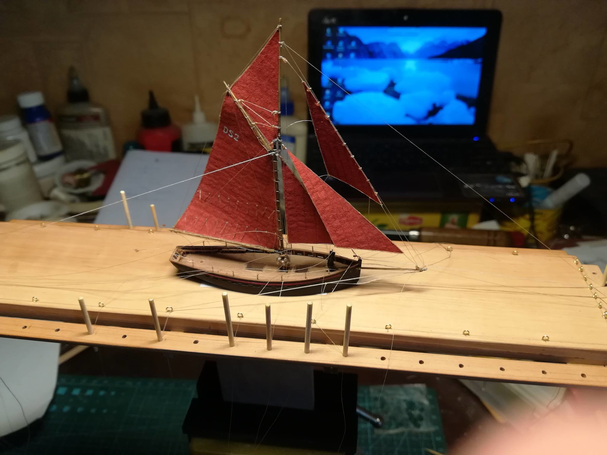
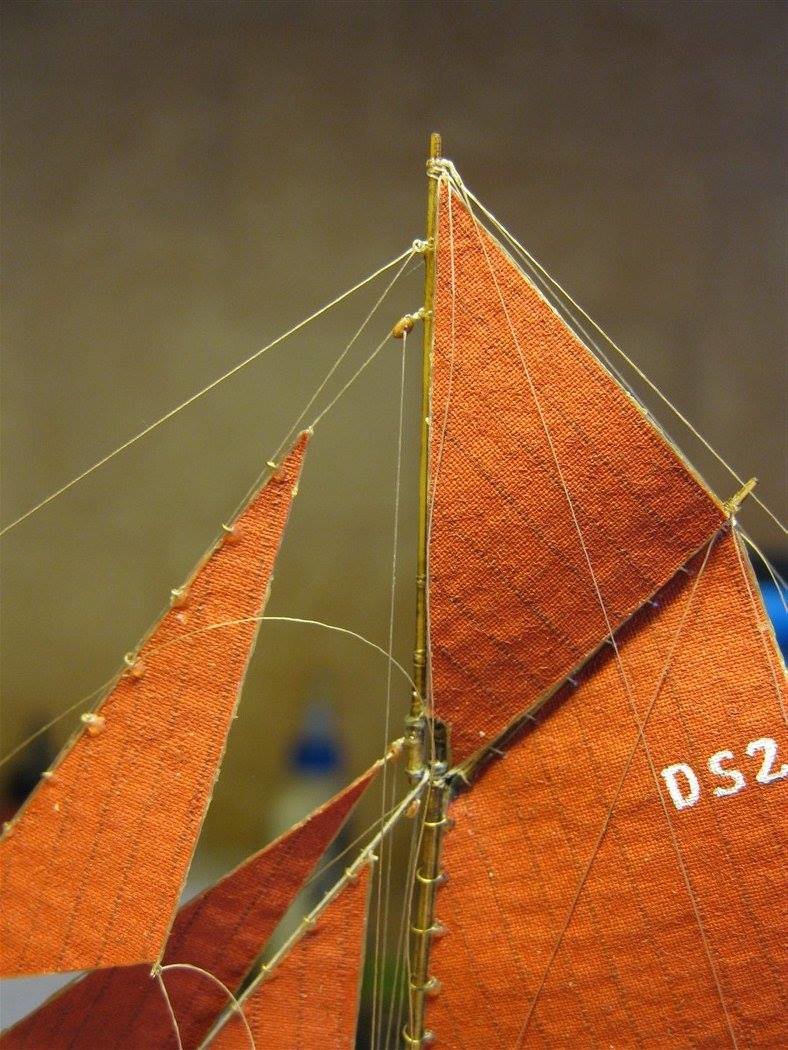
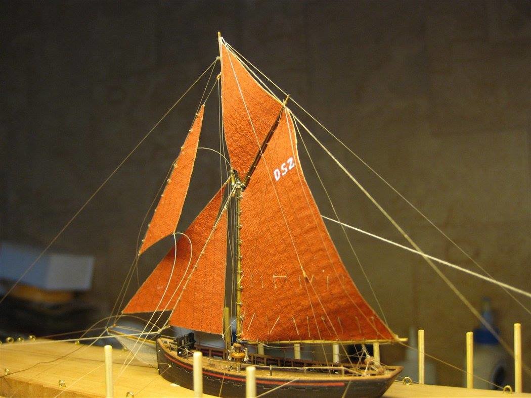
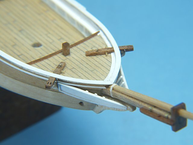
Pilot cutter Jolie Brise in a bottle - Scale 1/240
JerseyCity Frankie and 10 others reacted to IgorSky for a topic
Many thanks bluenoser! The work is slow, but, nevertheless, it is going A few days ago I was compelled to make building berth. This time the rigging turns out to be more complicated than I did before.


 11 points


.JPG.d9e5366de927e74777e7e1f3a19004e1.JPG)